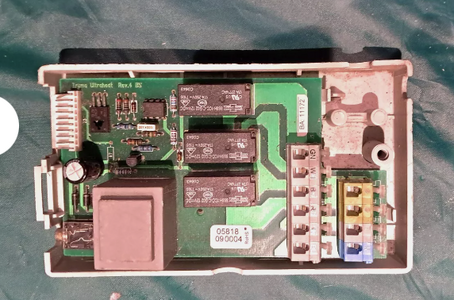
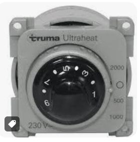
I was wondering if anyone has any IN DEPTH technical info regarding the system.
@ProfJohnL
The switch shows a heat setting variable between 1 and 9
The external switch selects wattage, 500, 1000, and 2000
Without looking I imagine that the relays on the board simply switch the two 1000 watt elements in different combinations,
In series for 2000 watts
In parallel for 500 watts
and only one on for 1000 watts
However I am looking for a wring diagram or detail diagram of the switch itself.
When adjusting between 1 and 9 what exactly is the output?
Is it a variable resistance or what?
A diagram and explanation of the whole system and how the 1 ~ 9 selection switch sets a control point and then where the thermocouple or other probe sits to measure the air temperature and work with that signal?
I see there is provision for an external air/room sensor:
What is that sensor T/C PT100 Thermister OR WHAT
How does that interact with the switch?
Any ideas.
Anyone welcome to comment.


