Unknown part at battery charger

Feb 24, 2024
4
1
15
Visit site
IMG_6084.jpeg
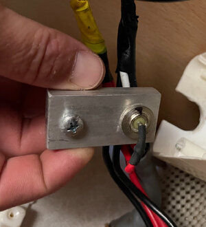
Hi everyone just wondering if anyone can tell me what this is in this image? Its wired to a Wialki battery charger- CC-1223 thanks
 

Attachments

  • IMG_6103.jpeg
    IMG_6103.jpeg
    1.2 MB · Views: 21
Last edited:
Nov 12, 2021
354
322
1,935
Visit site
The first thing that sprung to mind is that it's a sacrificial or galvanic anode. These are designed to reduce galvanic corrosion caused when a small electrical current is generated where two different metals are joined together. But, they are usually found on boats to protect metal parts that are submerged in water, especially seawater. They are also found in hot water systems to protect the water tank. But, I'm not sure why the one you have is fitted to your caravan like that unless it's intended to protect the chassis where the battery earth lead is connected to it.
Of course, it might not be a sacrificial anode though. Hopefully, someone here can give a more definitive answer.
 
Last edited:
Mar 14, 2005
17,947
3,309
50,935
Visit site
Hello Coromal,

This is is new to me, I have never seen anything like it previously in a caravan or motorhome. It raises a number of questions...

Based on the photos you have provided, it seems it's a piece of metal bar approx 20 mm x 40mm x 5mm with the appearance of aluminium.
It has two holes, one which has a nut and bolt securing a wire crimp connected to a purple wire.

The other hole is plain but has some device secured into it . The device seems to have a concentric construction with a central solder terminal. There is a on off white material surrounding the terminal filling in the space to tubular wall of the device. A red wire is connected to the devices terminal.

The construction of the device suggests it has an electrical function with its outer cylindrical case forming one of the electrical connections case . The size of it and the metal block also suggest its likely to get warm/hot when it does whatever it's designed to do.

My initial thoughts are is it a high power Diode, a thermal fuse , a temperature sensor, or even a lightning arrestor. For any of these functions it would almost certainly need to secured and protected to prevent accidental with any other wires or metallic parts.

I can't see any sort mounting or fixing for it, was it just floating on its wires?
Was it mounted or covered to prevent accidental contact with other wires or other metallic parts of the van?

Incidentally what make , model and year was the caravan?
 
  • Like
Reactions: Paullus1959
Aug 12, 2023
467
191
235
Visit site
Test with multimeter if it 0 Ohms between input and output then likely to be thermal fuse. Diode would be 0.2-0.7V using meters diode test and open circuit in reverse direction.
 
  • Like
Reactions: Dustydog
Feb 24, 2024
4
1
15
Visit site
Thanks everyone for your time. Its off a 2006 Coromal Lifestyle 605. It is mounted adjacent to the charger in a cupboard, under a white plastic wall mounted box. Like a junction box. There is a 3 way fridge adjacent to the cupboard. Not sure if it could have something to do with that?

Regarding the purple wire, I noticed a purple wire connected to the drawbar anderson plug positive side. Im not certain that it leads to the purple wire seen in the images as its hard to trace but ill do some investigating with a multimeter. So at the anderson plug on the drawbar there is your standard black neg and red positive, and also a purple soldered onto the lug with the red. My thoughts were an independent power cable to the 3 way fridge? I just dont know if this little alloy block in the photos has anything to do with it. Its my first caravan and only just purchased so trying to wrap my amateur head around it
 
  • Like
Reactions: Dustydog
Nov 11, 2009
21,202
6,719
50,935
Visit site
Thanks everyone for your time. Its off a 2006 Coromal Lifestyle 605. It is mounted adjacent to the charger in a cupboard, under a white plastic wall mounted box. Like a junction box. There is a 3 way fridge adjacent to the cupboard. Not sure if it could have something to do with that?

Regarding the purple wire, I noticed a purple wire connected to the drawbar anderson plug positive side. Im not certain that it leads to the purple wire seen in the images as its hard to trace but ill do some investigating with a multimeter. So at the anderson plug on the drawbar there is your standard black neg and red positive, and also a purple soldered onto the lug with the red. My thoughts were an independent power cable to the 3 way fridge? I just dont know if this little alloy block in the photos has anything to do with it. Its my first caravan and only just purchased so trying to wrap my amateur head around it
Do you know the previous owner, they may be able to help.
 
Mar 14, 2005
17,947
3,309
50,935
Visit site
As I understand it Anderson connectors are usually high amperage connectors that allow quick disconnect, and the mention of the fridge which running on 12V will use close to 10A of current suggest the device could well be a blocking diode.

This is an Australian caravan and their regulations regarding the segregation of tow vehicle and trailer habitation circuits may well be different to those allowed in the UK which is where this forum is based.

Where as in the UK there are several criteria that have to be met and we have to use a "habitation relay" , the Regs in Australia may allow a simple Diode block which only allows charge current to flow to the trailer but not back again to the tow vehicle.

The OP's reference to the purple wire apparently being soldered to the anderson connector, raised the possibility this is a modification to the original design. This is further supported when you look at the quality of the machining of the metal strip where the mystery device is located which shows signs of vice rash, and rough surface finish in the hole where the device is fitted. My guess is this is a non official modification, and could be to provide a separate 12V feed for something.
 

JTQ

May 7, 2005
3,412
1,233
20,935
Visit site
Initial reaction was that the bulk of the block infers it is related to high some current carrying function?
And it does look like it has, and forms a mount for a Thyristor,

I have little doubt it is some after-market add on. Its nature implying it was a DIY job. that severed some now long defunct purpose the installed required, but now nothing.
Not that that moves you on in any constructive way, sorry.

How it is integrated circuit-wise, might help in understanding the purpose.
 
Mar 14, 2005
17,947
3,309
50,935
Visit site
Initial reaction was that the bulk of the block infers it is related to high some current carrying function?
And it does look like it has, and forms a mount for a Thyristor,

I have little doubt it is some after-market add on. Its nature implying it was a DIY job. that severed some now long defunct purpose the installed required, but now nothing.
Not that that moves you on in any constructive way, sorry.

How it is integrated circuit-wise, might help in understanding the purpose.
I agree concerning the high current, but I can only see two connections which tends to discount a thyristor which normally has three connections.
 

JTQ

May 7, 2005
3,412
1,233
20,935
Visit site
Most of us get by without anything like it, so if I had purchased a van with it, the more so as installed here, it would be coming out and van put back to standard, at least if I could not find out what attributes it was bringing me.
 
Jul 18, 2017
13,201
3,776
40,935
Visit site
Most of us get by without anything like it, so if I had purchased a van with it, the more so as installed here, it would be coming out and van put back to standard, at least if I could not find out what attributes it was bringing me.
If there was a tendency for the voltage to spike every now and then maybe it could be a rectifier? Just guessing!
 
Mar 14, 2005
17,947
3,309
50,935
Visit site
If there was a tendency for the voltage to spike every now and then maybe it could be a rectifier? Just guessing!
A rectifier (incidentally a diode is a rectifier!) is often used in a fly back or snubber network to capture reverse polarity voltage spike that are produced when a current through an inductor is switched off. The circuit can "ring" as the magnetic flux field around the inductor collapses. Properly designed circuits that might have a voltage spike should also contain the snubber and not require one to be fitted externally in such an ad-hock manner as the OP's.

There also special components called Zenner Diodes which are used to shunt excess voltages/currents but again it's very unlikely any professional design would use a Zenner in such an isolated manner. It would normally be built into an appliance along with the other necessary components need for it to work safely and reliably.

The OP's discovery, whatever it is, has all the hallmarks of a non professional ad hoc solution.
 
  • Like
Reactions: Buckman
Nov 16, 2015
10,938
3,222
40,935
Visit site
It looks like a Zener diode that was used on 12v motor cycle systems.

 
Last edited:

TRENDING THREADS

Latest posts