-
We’re currently investigating an issue related to the forum theme and styling that is impacting page layout and visual formatting. The problem has been identified, and we are actively working on a resolution. There is no impact to user data or functionality, this is strictly a front-end display issue. We’ll post an update once the fix has been deployed. Thanks for your patience while we get this sorted.
You are using an out of date browser. It may not display this or other websites correctly.
You should upgrade or use an alternative browser.
You should upgrade or use an alternative browser.
Thetford toilet
- Thread starter Jamesl63
- Start date
Will help I’d you state which model it is
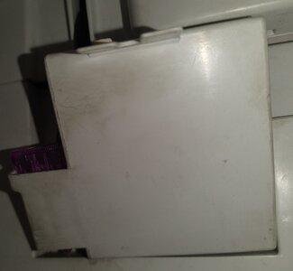
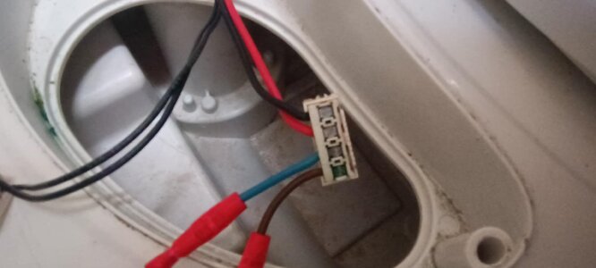
When you say you have checked the fuse is that the one in RH side of the cassette locker? its a 3A spade type. to check this remove the flush panel and test the pcb wires/socket to see if 12V is present (red and black wires) ?
Attachments
Yes that's the one tested fuse and it's fineWhen you say you have checked the fuse is that the one in RH side of the cassette locker? its a 3A spade type. to check this remove the flush panel and test the pcb wires/socket to see if 12V is present (red and black wires) ?
I'll try that next thank sCan you check if the 12vDC powering feed gets to the fuse, then to the motor's connections?
Ok as per previous posts I have done the following just to let you know I am still learning about the caravan and I appreciate your help on here
A I have changed the fuse for a new one 3 amp
B I have now gone inside checked with a meter and I am getting 13 volts into the toilet when I check
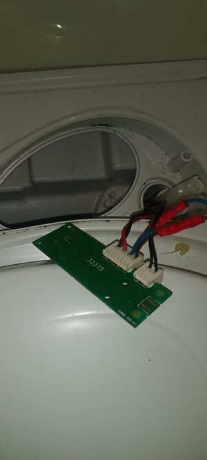
The only issue and I am assuming this might be my problem is the two fly leads out to the board are showing no reading I would have thought 13 volts should have been read
The board looks ok
Also I should have remembered how the board connects back I think it's sude but not sure what the two connection is for on the small side on the board is for
Thanks
A I have changed the fuse for a new one 3 amp
B I have now gone inside checked with a meter and I am getting 13 volts into the toilet when I check
The only issue and I am assuming this might be my problem is the two fly leads out to the board are showing no reading I would have thought 13 volts should have been read
The board looks ok
Also I should have remembered how the board connects back I think it's sude but not sure what the two connection is for on the small side on the board is for
Thanks
Attachments
-
 Messenger_creation_8ABD2C64-3D6F-4E26-91B4-2280ED56C016.jpeg53.2 KB · Views: 19
 -
 Messenger_creation_E3B22195-AE73-459F-BD89-F9F2BCFA00B7.jpeg108 KB · Views: 17
 -
 Messenger_creation_0CF36C37-E46A-42F8-A7DC-F2BD604057D8.jpeg116.5 KB · Views: 16
 -
 Messenger_creation_54DE928D-89AC-438A-86A9-4786495D6084.jpeg70.3 KB · Views: 14
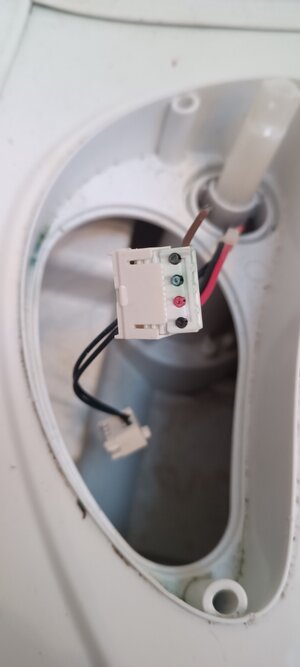
Sounds like the wires from the cassette (where the fuse is located )to the flush pcb have suffered a common problem - corrosion(blackening of the copper conductors ) and should be replaced . RE the two connectors on the small side of the PCB , it is a universal one which is used for different versions of the toilet , for instance a remote solenoid , vent kit and other options ( see the pads near the switch which is for a 20 pin chip - not fitted). so nothing is connected to them. the edge connectors fit with the leads facing down with the PCB component side up. the attached picture show the correct way (non component side up) the supply wires are on the right , then the pump wire ( brown blue two core) and the reed switch input (black) wires on the left.
Attachments
Sorry as I said was new to this
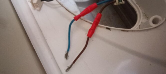
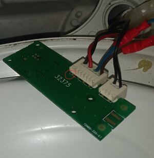
On my img below the red and black both have a voltage reading
But the blue and black fly leads that had a sleeve on them have no power reading
Should they not be feeding 12 volts to the PCB board or I have I got his wrong ?
On my img below the red and black both have a voltage reading
But the blue and black fly leads that had a sleeve on them have no power reading
Should they not be feeding 12 volts to the PCB board or I have I got his wrong ?
Attachments
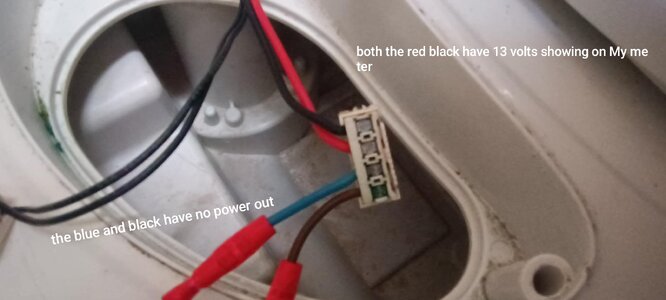
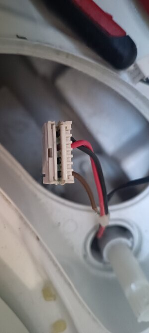
Red and black are the 12V supply wires from the cassette area (where the fuse and reed switch are located ) and the brown and blue wires with in the inline crimps on them should go to the pump inside the tank . The fact that they have the red crimp connectors on them shows the pump has been changed previously .Once you press the pcb mounted switch ,those two wires should have 12V between them. If you connect a pump and it fails to run then two things may cause this
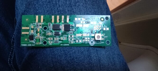
1. the PCB is faulty - faulty switch or the circuit is U/S - which looking at an image of your pcb is highly unlikely as it looks in good condition as does the switch and switching transistor.
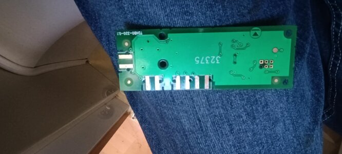
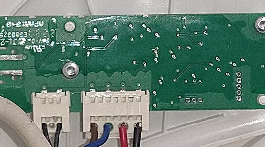
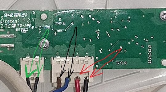
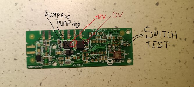
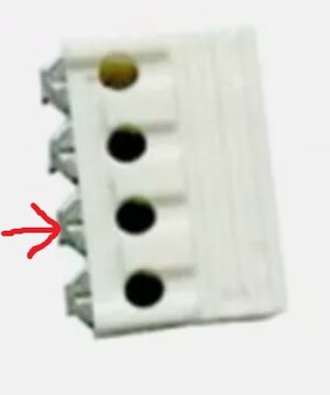
2. the voltage coming into the pcb on the red and black wires drops when under load , which can be cause by corrosion somewhere in the wires or the fuse pcb .In the attached photo the red arrow shows the supply wires, the black the pump output wires and the green the cassette full reed switch to the PCB mounted LED. Its a bit fiddly but if you can connect your multimeter to the red and black wires whilst connected to the pcb and with a pump also connected then when you press the flush switch on the pcb if the voltage drops ( say to 9v or less) you have a bad connection somewhere in the supply wires, iF it stays around 12V or around that the supply is OK retest on the pump wires (with a pump connected) , if that voltage doesn't reach about 11V then the short wires/crimps connectors are faulty.
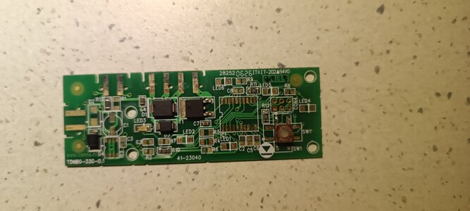
As an aside as your PCB is a later version than the one have images of could you please take another photo of the component side (similar to your posted image ending 57D8) with a better focus of the board and the components.
1. the PCB is faulty - faulty switch or the circuit is U/S - which looking at an image of your pcb is highly unlikely as it looks in good condition as does the switch and switching transistor.
2. the voltage coming into the pcb on the red and black wires drops when under load , which can be cause by corrosion somewhere in the wires or the fuse pcb .In the attached photo the red arrow shows the supply wires, the black the pump output wires and the green the cassette full reed switch to the PCB mounted LED. Its a bit fiddly but if you can connect your multimeter to the red and black wires whilst connected to the pcb and with a pump also connected then when you press the flush switch on the pcb if the voltage drops ( say to 9v or less) you have a bad connection somewhere in the supply wires, iF it stays around 12V or around that the supply is OK retest on the pump wires (with a pump connected) , if that voltage doesn't reach about 11V then the short wires/crimps connectors are faulty.
As an aside as your PCB is a later version than the one have images of could you please take another photo of the component side (similar to your posted image ending 57D8) with a better focus of the board and the components.
Attachments
Img as requested
Still not working but I did not try all connected with a meter not sure how to do that
I think I know what you meant all connected and press flush with red and black connected to meter👍
Still not working but I did not try all connected with a meter not sure how to do that
I think I know what you meant all connected and press flush with red and black connected to meter👍
Attachments
Last edited:
Thanks for the photos , very clear.
To measure the voltages whist connected can be tricky . Being an electronics engineer (retired) I find it easy as I use various techniques so I'll try and explain
1. I have needle probes which be inserted into the end of the cables or connectors to get at the metal conductors.
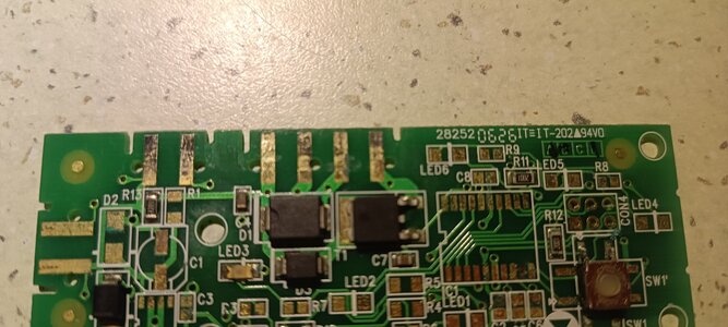
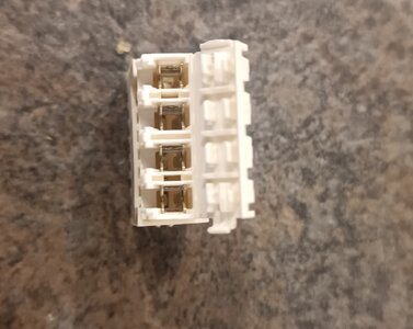
2. On the attached photo the ends of the pcb fingers are just visible ( circled in red) you can press your multimeter probes on them to measure voltages with the connectors connected.(Note all the copper tracks which are green are covered in an insulating lacquer so reading can't be taken on these)
3.on the component side I have marked up suitable test points and marked them up on the second photo. For the switch test, with no power to the pcb, set your multimeter to ohms and when the probes are on the circled pads next to the switch press the switch, the reading should change from infinity to a low value >10 ohms.
To measure the voltages whist connected can be tricky . Being an electronics engineer (retired) I find it easy as I use various techniques so I'll try and explain
1. I have needle probes which be inserted into the end of the cables or connectors to get at the metal conductors.
2. On the attached photo the ends of the pcb fingers are just visible ( circled in red) you can press your multimeter probes on them to measure voltages with the connectors connected.(Note all the copper tracks which are green are covered in an insulating lacquer so reading can't be taken on these)
3.on the component side I have marked up suitable test points and marked them up on the second photo. For the switch test, with no power to the pcb, set your multimeter to ohms and when the probes are on the circled pads next to the switch press the switch, the reading should change from infinity to a low value >10 ohms.
Attachments
Thanks ian for the explanation so by putting the probes on the two reds will show me power coming in to the board and the two blacks out the power to the pump unitThanks for the photos , very clear.
To measure the voltages whist connected can be tricky . Being an electronics engineer (retired) I find it easy as I use various techniques so I'll try and explain
1. I have needle probes which be inserted into the end of the cables or connectors to get at the metal conductors.
2. On the attached photo the ends of the pcb fingers are just visible ( circled in red) you can press your multimeter probes on them to measure voltages with the connectors connected.(Note all the copper tracks which are green are covered in an insulating lacquer so reading can't be taken on these)
3.on the component side I have marked up suitable test points and marked them up on the second photo. For the switch test, with no power to the pcb, set your multimeter to ohms and when the probes are on the circled pads next to the switch press the switch, the reading should change from infinity to a low value >10 ohms.
Thanks Ian I'll tackle it tommorow and see how I get on
🍺🍺 A virtual beer for your help
Hi Ian some success but I have a new problemThanks Ian I'll tackle it tommorow and see how I get on
🍺🍺 A virtual beer for your help
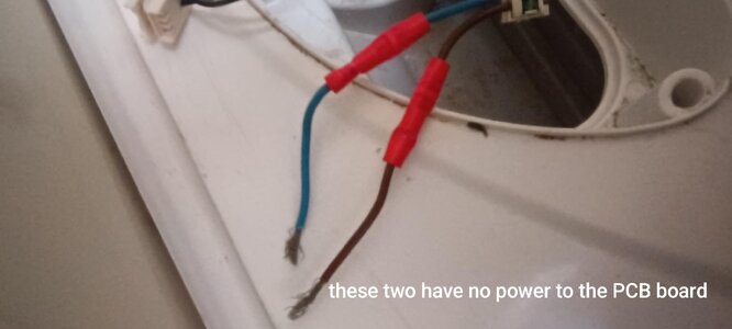
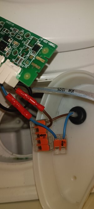
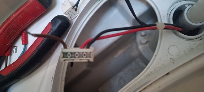
All the readings were as you said they should be so I started to tackle your final solution. Of the fly lead
I thought it would be best to remove the crimp connector in case that was damaged or not getting a connection
All was going fine until the blue wire came away from the connector
I thought there might be a push for it a screw to attach but neither
Attachments


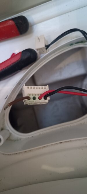
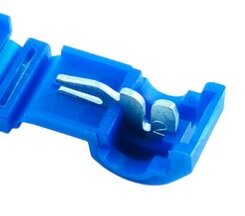
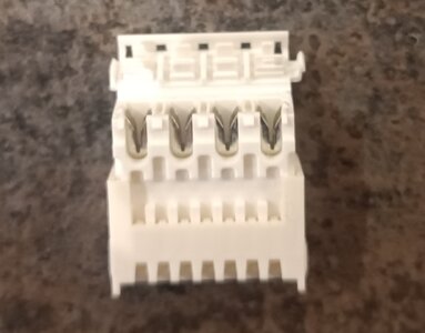
It's called an IDC (Insulation Displacement Connector) There is a cover which clips on and the way it works is:- The cover in the supplied position allows the whole cable to push into the hole and when all are in, a special crimp tool then presses the cover down to the closed position and this forces the wires onto a 'blade with a slot' , this cuts through the insulation and the blade 'slot' then connects to the copper conductors( see photo of a Scotchlok which uses the same principle) . If you can prise the cover off ( there are sometimes little tabs which can be lifted to release the cover) then you can insert the wire onto the blade put the cover back on and using a vice ( which is probably not an option in this case) or a pair of pliers/mole grips squeeze the cover to force the new wire on and into the blades slot . Alternatively you can buy replacement connectors off ebay from jnc camping and others - https://www.ebay.co.uk/itm/187244966547 is one example.
On the thetford connectors the bits that press the cable against the blade are individual so a bit more fiddly to raise one back up - see second photo) so a small watch screwdriver is useful to prise it back up. One of the downsides of these IDC connectors is that sometimes the blade nips the copper conductors and over time these can snap off , if the cables are moved a lot (vibration). I used to get this a lot in my professional life with ribbon cables on parallel communication cables in computer/control systems, one open circuit wire in 10/14/24/28 way cable could stop the system dead in its tracks, so I got pretty good at removing the connector and re-crimping it back on . Don't be tempted to solder the wires onto the pcb edge 'fingers' (seen that done!) The copper tracks are glued onto the board and heat and mechanical stress can lift them off . when soldering wires to pcbs they either need to go through a hole or have some mechanical support , such as glue or high modulus silicone adhesive/sealant ( not simple bath sealant) as well .
On the thetford connectors the bits that press the cable against the blade are individual so a bit more fiddly to raise one back up - see second photo) so a small watch screwdriver is useful to prise it back up. One of the downsides of these IDC connectors is that sometimes the blade nips the copper conductors and over time these can snap off , if the cables are moved a lot (vibration). I used to get this a lot in my professional life with ribbon cables on parallel communication cables in computer/control systems, one open circuit wire in 10/14/24/28 way cable could stop the system dead in its tracks, so I got pretty good at removing the connector and re-crimping it back on . Don't be tempted to solder the wires onto the pcb edge 'fingers' (seen that done!) The copper tracks are glued onto the board and heat and mechanical stress can lift them off . when soldering wires to pcbs they either need to go through a hole or have some mechanical support , such as glue or high modulus silicone adhesive/sealant ( not simple bath sealant) as well .
Attachments

It's called an IDC (Insulation Displacement Connector) There is a cover which clips on and the way it works is:- The cover in the supplied position allows the whole cable to push into the hole and when all are in, a special crimp tool then presses the cover down to the closed position and this forces the wires onto a 'blade with a slot' , this cuts through the insulation and the blade 'slot' then connects to the copper conductors( see photo of a Scotchlok which uses the same principle) . If you can prise the cover off ( there are sometimes little tabs which can be lifted to release the cover) then you can insert the wire onto the blade put the cover back on and using a vice ( which is probably not an option in this case) or a pair of pliers/mole grips squeeze the cover to force the new wire on and into the blades slot . Alternatively you can buy replacement connectors off ebay from jnc camping and others - https://www.ebay.co.uk/itm/187244966547 is one example.
On the thetford connectors the bits that press the cable against the blade are individual so a bit more fiddly to raise one back up - see second photo) so a small watch screwdriver is useful to prise it back up. One of the downsides of these IDC connectors is that sometimes the blade nips the copper conductors and over time these can snap off , if the cables are moved a lot (vibration). I used to get this a lot in my professional life with ribbon cables on parallel communication cables in computer/control systems, one open circuit wire in 10/14/24/28 way cable could stop the system dead in its tracks, so I got pretty good at removing the connector and re-crimping it back on . Don't be tempted to solder the wires onto the pcb edge 'fingers' (seen that done!) The copper tracks are glued onto the board and heat and mechanical stress can lift them off . when soldering wires to pcbs they either need to go through a hole or have some mechanical support , such as glue or high modulus silicone adhesive/sealant ( not simple bath sealant) as well .
Yes I managed to get the cover off but when I looked I could not see a way to get the small amount of cable left in or to be able to insert a new pieceIt's called an IDC (Insulation Displacement Connector) There is a cover which clips on and the way it works is:- The cover in the supplied position allows the whole cable to push into the hole and when all are in, a special crimp tool then presses the cover down to the closed position and this forces the wires onto a 'blade with a slot' , this cuts through the insulation and the blade 'slot' then connects to the copper conductors( see photo of a Scotchlok which uses the same principle) . If you can prise the cover off ( there are sometimes little tabs which can be lifted to release the cover) then you can insert the wire onto the blade put the cover back on and using a vice ( which is probably not an option in this case) or a pair of pliers/mole grips squeeze the cover to force the new wire on and into the blades slot . Alternatively you can buy replacement connectors off ebay from jnc camping and others - https://www.ebay.co.uk/itm/187244966547 is one example.
On the thetford connectors the bits that press the cable against the blade are individual so a bit more fiddly to raise one back up - see second photo) so a small watch screwdriver is useful to prise it back up. One of the downsides of these IDC connectors is that sometimes the blade nips the copper conductors and over time these can snap off , if the cables are moved a lot (vibration). I used to get this a lot in my professional life with ribbon cables on parallel communication cables in computer/control systems, one open circuit wire in 10/14/24/28 way cable could stop the system dead in its tracks, so I got pretty good at removing the connector and re-crimping it back on . Don't be tempted to solder the wires onto the pcb edge 'fingers' (seen that done!) The copper tracks are glued onto the board and heat and mechanical stress can lift them off . when soldering wires to pcbs they either need to go through a hole or have some mechanical support , such as glue or high modulus silicone adhesive/sealant ( not simple bath sealant) as well .
Attachments
Yes I managed to get the cover off but when I looked I could not see a way to get the small amount of cable left in or to be able to insert a new piece

Thanks Ian I tried but it's so tight in there so I am going to order a new oneNo they dont , You need to lift the individual 'clamp ' by inserting a small watch screwdriver blade to lift it - so its in the position shown by red arrow not easy, or buy the connector kit
I assume I will need to order a crimp tool as well are these just standard or will I require a special type
👍
I haven't used an idc crimp tool in years as they are mainly used for the larger ribbon cables use in computers ( 16 way and above) as I said I use a small vice or even electricians pliers will do the job as its only 4 wires so they will exert enough force. You could buy a IDC crimp tool for about £10 on CPC Farnell part number TL08619, but it will just gather dust once used.
Attachments

Apologies late into this but sometimes a revisit can help. I know you say you have checked this but have you checked the terminals connections to the fuse in the waste tank compartment. Electrical contact spray? Works wonders😉 Hope you solve it👍
TRENDING THREADS
-
-

-
-

-
-
Mandatory eye tests for drivers over 70 being proposed by HMG. Good or bad?
- Started by Dustydog
- Replies: 201
-