A number of regular Forumites are well versed in the technical aspects of this Truma water heater. Many have contributed excellent technical advice and guidance.
I have noticed on occasion some misunderstandings by newer Forumites , that left unchecked may result in a serious incident.
Let me kick the ball in the air and welcome as much technical input from the Formites please.
If what I say is very basic and elementary then I do so deliberately to ensure there is no ambiguity.. If I am wrong I apologise now.
The heater has a blue cold water feed pipe from the cold water supply source and a hot water exit pipe to the taps.
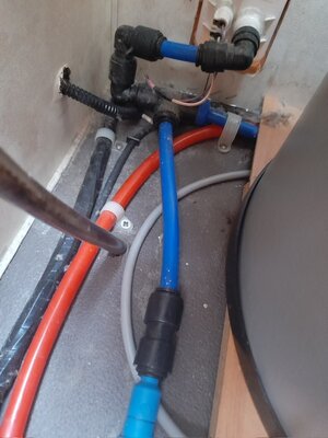
Most of the Truma Ultraheat units I have owned have a Non Return Valve fitted in line in the blue cold water supply pipe.
Usually near the top of the heater tank will be a three way plumbing type joint.
This joint contains the pressure relief valve .
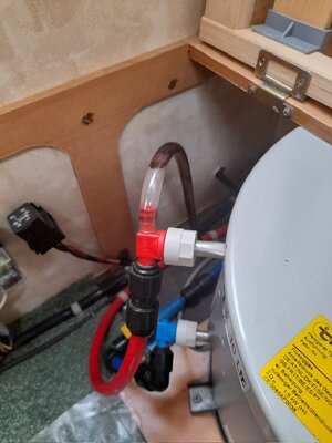
Connection one exits the tank with hot water, connection two feeds a red water pipe to the taps and the third connection is a clear plastic pipe which allows over pressured hot water to escape when pressure relief valve activates.
This pipe does not feed the hot taps. It is as a mechanism to avoid over pressurisation of the tank and allows excess pressure and hot water to escape.
I am not aware of any rogue foreign parts that could be fitted to either the hot or cold side. If the NRV was fitted to the red pipe then the system wouldn’t work! Similarly if the three way pressure relief unit was fitted to the cold side ?? Would the tank ever fill?
Truma in their handbook include installation instructions which are pretty clear. Hopefully these photos will help
I hope this helps and avoids anyone mixing the two up. Unlikely but perhaps not knowing is dangerous. Maybe Truma should follow the aircraft industry and ensure the parts can’t be cross fitted in error.
The NRV fitted In line in the blue cold water feed


Three way hot water outlet with red pipe to hot water taps and clear pipe for exit of hot water /air if PRV operates
I have noticed on occasion some misunderstandings by newer Forumites , that left unchecked may result in a serious incident.
Let me kick the ball in the air and welcome as much technical input from the Formites please.
If what I say is very basic and elementary then I do so deliberately to ensure there is no ambiguity.. If I am wrong I apologise now.
The heater has a blue cold water feed pipe from the cold water supply source and a hot water exit pipe to the taps.
Most of the Truma Ultraheat units I have owned have a Non Return Valve fitted in line in the blue cold water supply pipe.
Usually near the top of the heater tank will be a three way plumbing type joint.
This joint contains the pressure relief valve .
Connection one exits the tank with hot water, connection two feeds a red water pipe to the taps and the third connection is a clear plastic pipe which allows over pressured hot water to escape when pressure relief valve activates.
This pipe does not feed the hot taps. It is as a mechanism to avoid over pressurisation of the tank and allows excess pressure and hot water to escape.
I am not aware of any rogue foreign parts that could be fitted to either the hot or cold side. If the NRV was fitted to the red pipe then the system wouldn’t work! Similarly if the three way pressure relief unit was fitted to the cold side ?? Would the tank ever fill?
Truma in their handbook include installation instructions which are pretty clear. Hopefully these photos will help
I hope this helps and avoids anyone mixing the two up. Unlikely but perhaps not knowing is dangerous. Maybe Truma should follow the aircraft industry and ensure the parts can’t be cross fitted in error.
The NRV fitted In line in the blue cold water feed


Three way hot water outlet with red pipe to hot water taps and clear pipe for exit of hot water /air if PRV operates
Last edited:

