What is this fuse for? Burstner C530tk tripping rcd

Jul 22, 2021
4
0
10
Visit site
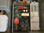
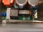
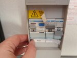
Can anyone tell me what this 5A fuse is for? It's the missing one at the bottom, shown in the close up pic.

Just checking the electrics on our 2006 burstner c530tk, which we bought during lockdown and have been doing up, and have found a problem. This 5a fuse was out, when we put it back the circuit breaker on the right hand side trips. According to the handwritten label that circuit breaker is for the water heater, fridge and charger. The water heater and fridge are working fine, and disconnecting the charger doesn't stop the switch from tripping. But if I knew what the fuse was for I'm sure that would help! Or even better, if somebody out there has a wiring diagram - the manual is not much help here.
 

Attachments

  • 20210722_122507.jpg
    20210722_122507.jpg
    209.1 KB · Views: 33
  • 20210722_122540.jpg
    20210722_122540.jpg
    150.1 KB · Views: 31
  • 20210722_122513.jpg
    20210722_122513.jpg
    115.4 KB · Views: 32
Jun 16, 2020
4,702
1,864
6,935
Visit site
How do you know that that fuse should be 5amp? Usually these fuses on the printed circuit board are very small amperage and slow blow. Presumably the charger does not work. This could be why the fuse has been removed. It seems odd to me that the other 10 amp low voltage fuses are on the circuit board and unprotected. Presumably, there is a cover for the panel, does that not have any info on it?

John
 
Jul 22, 2021
4
0
10
Visit site
Hi John thanks for answering! I have no idea if its supposed to be a 5a fuse just that's what was on it. Panel cover has no information whatsoever. I have a wiring diagram from the original manual which I have, but it doesn't explain the fuse.
 
Jul 22, 2021
4
0
10
Visit site
Charger appears to be working fine as well, as far as I can tell - we've literally just put a new battery on it today.
I've no way of knowing if the charger is working. We've disconnected the fridge, heater, water heater and the charger/12v supply and it's still tripping the mcb. 12v circuit on the battery lights and water pumps work fine. 230v side plugs and appliances appear to be working fine.
 
Last edited:
Jun 20, 2005
17,391
3,567
50,935
Visit site
Check the charge output with a multimeter.
You could contact the Burstener owners club for the correct wiring diagram. Do you have an inline fuse near the battery?
Test the Breaker to make it is ok.
 

Damian

Moderator
Mar 14, 2005
7,510
936
30,935
Visit site
Moderator Note: A posting by a company has been removed as self advertising is NOT permitted on the forum .
 
Oct 8, 2006
1,774
544
19,935
Visit site
The device is known as a switched mode power supply or SMPS. It has high voltages in it and should have an earthed metal protective cover over the top. The fuse will be the incoming mains supply fuse. Given that the PSU probably supplies about 16A at 12V, that is about 200W, I would have expected the fuse to be 2A probably slow-blow (in which case the fuse rating would be preceded by T.) There will be quite a large surge at switch on as the brown capacitors charge up hence a time-delay fuse signified by the T.

An SMPS takes the incoming 240Vac mains and converts it to d.c. - usually around 380Vdc which charges up the two large brown capacitors. This supply is then chopped up at high frequency - typically in excess of 100KHz - and used to feed a transformer which produces an output of around 20Vdc or so. This is then regulated to give you the 13.8V that the SMPS usually outputs.

The 'chopping' is done by the small power transistor that is bolted to the chassis close to the brown capacitors: the regulation is done by the larger transistor near the two smaller black capacitors. Note that both transistors are insulated from the chassis, the larger by an insulating heat-conductive washer, the smaller by being in an insulated plastic package. The transformer between the two transistors is what does the voltage change: if it were designed to run at 240V 50Hz mains it would be at least twice the size of the whole SMPS, would be very heavy, and would probably need a cooling fan. Running the switching at high frequencies is considerably more efficient. Failure of the mains-side 'chopping' transistor is the most common cause of failure. Being a high voltage device they usually go short circuit which would cause the fuse to blow, or indeed the MCB to trip as it will work much more quickly than the fuse.

The red-ish 'transformer' in the lower left corner of the first picture is part of the filtering system to ensure that the high-frequency switching does not escape onto the mains.

The small black round component with a cross hole in the middle is the adjustment control for the output voltage.

As I said at the start, there are high voltages in this device - the brown capacitors can hold charge at nearly 400V for a long time after mains is removed, so EXTREME CARE is required.

Finally look at the device labelling. If it does not show what the current capacity is it might show the power by virtue of its model number. For example 180-12 would suggest 180W at 12V or roughly 15A output.
 
Mar 14, 2005
17,694
3,127
50,935
Visit site
I agree with Woodentop's description.

I would add the title of the thread is misleading as its not the RCD that is shown a tripping, it the MCB and indicates the circuit is drawing too much current, this could be why the fuse had been removed.

Like Woodedntop I do urge extreme caution because the components in these SMPS's do operate at very high voltages, and capacitors can contain more than enough charge to be lethal, so tinkering with such things should only be done by someone who knows how to manage these risks.

I appreciate this is a Burstner caravan and continental wiring practices might be different to the UK's, but the visible traces on the PCB around the fuse and the mains wiring block seem to suggest the blue wire (which in the UK is normally the neutral) is connected to the fuse rather than the Brown.

This makes me wonder if someone has been tampering and rewired it incorrectly.

I strongly suggest if you are not competent with electrics you should refer it to someone who is.
 
  • Like
Reactions: Dustydog
Oct 8, 2006
1,774
544
19,935
Visit site
Prof you have come across the usual European lack of understanding/training.
Because most European wiring is radial (rather than ring as it is here) and <every> outlet socket has a double pole MCB of its own, it is quite normal to put whichever wire they feel like into whichever socket - although if an earth is present they usually get that right! This is one of the reasons that those of us who cross the channel carry a mains tester to ensure the polarity is correct!
The annoying thing is that the EU comes out with the CEE17 blue connectors that are very clearly marked L and N but few electricians take any notice.
I rest my case M'lud.
 
  • Like
Reactions: Hutch and Dustydog
Jun 16, 2020
4,702
1,864
6,935
Visit site
Prof you have come across the usual European lack of understanding/training.
Because most European wiring is radial (rather than ring as it is here) and <every> outlet socket has a double pole MCB of its own, it is quite normal to put whichever wire they feel like into whichever socket - although if an earth is present they usually get that right! This is one of the reasons that those of us who cross the channel carry a mains tester to ensure the polarity is correct!
The annoying thing is that the EU comes out with the CEE17 blue connectors that are very clearly marked L and N but few electricians take any notice.
I rest my case M'lud.

I once went to plug into a multi socket post in France. The plastic was broken and there was a gaping hole in the hexagonal post. It was easy to see the wiring inside. For ease, it was wired with connections which were adjacent to each socket. This meant that every other socket had reverse polarity. So at least easy to find a suitable one. The fact that the post was so damaged did not seem to be of concern to the site.

John
 
Jul 22, 2021
4
0
10
Visit site
Thank you very much to Woodentop, that is extremely helpful. I think we've reached the limit of what's possible to DIY on this thing. As of yet all we've done is replace the fuse and check various appliances. Do you think it would be possible to replace the whole board with something UK spec, or just more modern? And while I'm here can anyone recommend someone to do that job up in Lancashire?
 
Oct 8, 2006
1,774
544
19,935
Visit site
The only problem - if it is that - that you have is that there are a lot of outlet connections. At a guess each one is fed by its own fuse in the +ve leg given there are five fuses present. Problem is there are 5 whites (white is -ve in a caravan) and four white/red and three blues. You need to look more closely at the printing on the circuit board for each connection.
Some more specialist SMPS units have the main outputs and at least one sensing wire on each side. If there is a long cable run there could be voltage drop, so the sensing connections use a thin twin wire and are connected to the output cables at the remote end. Thence if the PSU detects that the voltage at the remote end is lower than it should be it will increase the unit main output to bring the remote end up to spec. There is almost zero voltage drop on the sensing cable as the current is in microamps.

You might be better to see if you can find an electronics repair workshop who can fix that unit, then you will still have full connection reliability. If it is a failed switching transistor to anyone in electronics it is little more than 30 mins to fix assuming the correct replacement component is to hand.

If not that then a replacement unit of some sort will have to be sourced and a fuse array found to connect the outputs so that they all stay protected.

Other readers will probably suggest contacting Apuljack Engineering who make caravan power supplies but you still have to resolve the connection issue - unless of course they can fix your unit for you which their web site suggests they can/will. They have a Taunton postcode.
 
Jun 16, 2020
4,702
1,864
6,935
Visit site
Years ago I had a charger unit fail in a Unicorn. (It looked nothing like the OP’s). The distribution being separate from the unit. So for me it was an easy matter to remove it as a whole.

Instead of paying £80 plus for a replacement. I found an electronics guy locally who worked from home. He had never worked on one before. But had no problem getting some info from forums and replacing two components. One was obviously burnt out. The other he had to deduce.

If this one is not so easy to change off the shelf. Perhaps its a way forward. Particularly if it can be disconnected and removed easily enough.

John
 
Jun 20, 2005
17,391
3,567
50,935
Visit site
So true John. Local knowledge.
Someone did offer to help but the post was removed as it breached the Forum rules. Quite correct but maybe if there was a method of contact without breaching our rules it may help the OP.
 

Damian

Moderator
Mar 14, 2005
7,510
936
30,935
Visit site
Someone did offer to help but the post was removed as it breached the Forum rules

The posts were removed as the "someone" was a business self promoting itself without authorisation from the owners of the website, probably because advertising costs money, and we get quite a lot of people who try and circumvent the rules.

Firms that are recommended by forum users from personal knowledge and dealing with them are allowed as it is not the firm doing the advertising.

Apuljack and Gary are two such people who have been recommended by forum users, including myself, as they provide a trusted good service.
 

TRENDING THREADS