New Thetford C260 PCB Connectors.

Apr 13, 2009
258
15
18,685
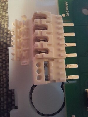
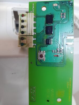
Just when you think all is fixed??? One of the electric wires of the flush pcb had broken off last week. I had no other option, I thought?, but to solder the wires onto the pcb directly. I must have overheated the board as the Red wire, the one that came off it's connector, has come off again. I need to know where some connectors, a Two and a Four, can be purchased, with leads attached? Anyone please?
 
Nov 11, 2009
23,600
8,126
50,935
I've had the same and have ordered this. I'm hoping it's the same connector.

It’s not available on the ebay link, but at least it’s identified a Thetford connector spares kit tyat may be available from other suppliers.
 
Apr 17, 2025
15
5
15
Oh well done! I've followed you're lead and bought the same? Be here tomorrow. Easy to mount on the wires are they?
Yes, You don't even need to strip the wires. You can just push the wires down into the connectors and then close the connector cover. I didn't bother using the other bit in the bag as it probably wouldn't fit then.
 
  • Love
Reactions: TerryIvybridge
Apr 13, 2009
258
15
18,685
Yes, You don't even need to strip the wires. You can just push the wires down into the connectors and then close the connector cover. I didn't bother using the other bit in the bag as it probably wouldn't fit then.
Hello again? I've received the pcb and connectors now, been stuck in the Post I assume? No instructions and no help forthcoming from Thetford on how to fit wires into the connectors? Can you help please?
 
Apr 17, 2025
15
5
15
Yes, of course. What you need to do is take the 4 wires from the caravan loom (Red and 3 black wires) and check which is the GND for the +12v (I used a multi-meter for this purpose between red and each of the blacks). Once I'd found that out I marked those as such (with a bit of tape I'd suggest)

I'd then suggest to cut the 4 wires clean to the same length and start to put them into the connector. Make sure that the Red wire goes into the connector that will be contacting on the board the furthest from the pump connector, then the GND on the next one. The remaining two connections are the other two black wires - these go to a switch that tells the board when the cassette is full.

You don't need to strip the wires, instead you place them into the connector and push them down so that the metal pieces the insulation and makes contact with the wire inside. Once all wires are in and you close the lid it pushes them all the way down into the connector and completes the connection.

Also, remember to make sure you wire the connector the right way around as the wires need to connect away from from the plastic part.

You'll only need one piece from that connector kit.
ThetfordToiletConnector.png
 
Last edited:
Apr 13, 2009
258
15
18,685
Yes, of course. What you need to do is take the 4 wires from the caravan loom (Red and 3 black wires) and check which is the GND for the +12v (I used a multi-meter for this purpose between red and each of the blacks). Once I'd found that out I marked those as such (with a bit of tape I'd suggest)

I'd then suggest to cut the 4 wires clean to the same length and start to put them into the connector. Make sure that the Red wire goes into the connector that will be contacting on the board the furthest from the pump connector, then the GND on the next one. The remaining two connections are the other two black wires - these go to a switch that tells the board when the cassette is full.

You don't need to strip the wires, instead you place them into the connector and push them down so that the metal pieces the insulation and makes contact with the wire inside. Once all wires are in and you close the lid it pushes them all the way down into the connector and completes the connection.

Also, remember to make sure you wire the connector the right way around as the wires need to connect away from from the plastic part.

You'll only need one piece from that connector kit.
View attachment 8789
Thank you so much KJ! That's a big help. I've taken photos and steps to make sure I re-attach in the correct order. Your photo explains all.
 
Last edited:
Apr 13, 2009
258
15
18,685
I have to fit both the four wires and the two wires. In this configuration KJ. So just to clarify, on the four, the wires push down into the joint directly from above and then close that back piece up. The Two joint being slightly different, the wires go into the holes and when it is pushed onto the board, that secures or traps the wires? Have I got that right please? Terry.
 

Attachments

  • 20250507_222332.jpg
    20250507_222332.jpg
    170.5 KB · Views: 2
  • 20250423_185809.jpg
    20250423_185809.jpg
    1.3 MB · Views: 2

TRENDING THREADS

Latest posts